XXXXXXXXXXXXXXXXXXXXXXXXXXXXXXXXXXXXXXXXXXXXXXXXXXXXXXXXXXXXXXXXXXXXXXXXXXXXXXXXXXXXXXXXXXXXXXXXXXXXXXXXXXXXXXXXXXXXXXXXXXXXXXXXXXXXXXXXXXXXXXXXXXXXXXXX''"> The Fabric Draping Process
Note: | Material Models for Draping. |
The fabric draping process can be split into two sections:
1. A Local draping mechanism
2. A Global draping procedure
Local Draping
Local draping is concerned with fitting a small section of material to a generally curved surface. If the surface has nonzero Gaussian curvature, the material element must shear in its plane to conform to the surface. This deformation is highly dependent on the microstructure of the material. As a result, local shearing behavior can be regarded as a ply material property.
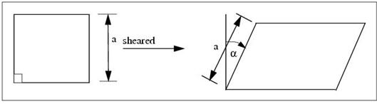
Figure 5‑2 Scissor Draping Mechanism
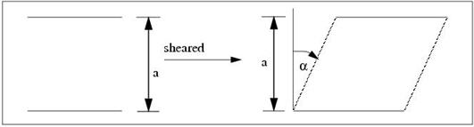
Figure 5‑3 Slide Draping Mechanism
MSC.Laminate Modeler currently supports two local draping algorithms: scissor and slide draping. For scissor draping, an element of material which is originally square shears in a trellis-like mode about its vertices to form a rhombus. In particular, the sides of the material element remain of constant length. This type of deformation behavior is characteristic of woven fabrics which are widely used to manufacture highly-curved composite components.
For slide draping, two opposite sides of a square material element can slide parallel to each other while their separation remains constant. This is intended to model the application of parallel strips of material to a surface. It can also model, very simply, the relative sliding of adjacent tows making up a strip of unidirectional material.
When draping a given surface using the two different local draping algorithms, the shear in the plies builds up far more rapidly for the slide draping mechanism than for the scissor draping mechanism. This observation is compatible with actual manufacturing experience that woven fabrics are more suitable for draping curved surfaces than unidirectional pre-pregs.
For small deformations, the predictions of the different algorithms are practically identical. Therefore, it is suggested that the scissor draping algorithm be used in the first instance.
Global Draping
Global draping is concerned with placing a real sheet of material onto a surface of general curvature. This is not a trivial task as there are infinite ways of doing this if the surface has nonzero Gaussian curvature at any point. Therefore, it is important to define procedures for the global draping simulation which are reproducible and reflect what can be manufactured in a production situation. As a result, global draping behavior can be regarded as a manufacturing, rather than material, property.
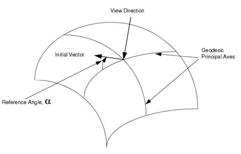
MSC.Laminate Modeler currently supports three different global draping algorithms: Geodesic, Planar and Energy. For the Geodesic global draping option, principal axes are drawn away from the starting point along geodesic paths on the surface (i.e., the lines are always straight with respect to the surface). Once these principal axes are defined, there is then a unique solution for draping the remainder of the surface. This may be considered the most “natural” method and appropriate for conventional laminating methods. However, for highly‑curved surfaces, the paths of geodesic lines are highly dependent on initial conditions and so the drape simulation must be handled with care.
Figure 5‑4 Geodesic Global Draping
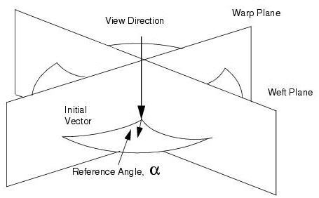
For the Planar global draping option, the principal axes may be defined by the intersection of warp (and weft for scissor draping) planes which pass through the viewing direction. This method is appropriate where the body has some symmetry, or where the layup is defined on a space-centered rather than a surface‑centered basis.
Figure 5‑5 Planar Global Draping
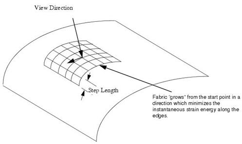
Finally, the Energy global draping option is provided for draping highly-curved surfaces where the manufacturing tolerances are necessarily greater. Here, the draping proceeds outwards from the start point, while the direction of draping is controlled by minimizing the shear strain energy along each edge.
Figure 5‑6 Energy Global Draping
Note that all draping simulations are discrete and use a specific step length. A default value is calculated on the basis of the area of the selected region. This may be modified or overridden, using the step length databox on the Additional Controls/Geometry form.
The sections above relate only to how the fabric algorithm works internally. When the graphics are drawn to the screen, they are drawn in the same manner for all of the selected types, if applicable. The fabric drawing to the screen has no relevance to the method that the fabric generation routine executed. In particular, do not expect to see the fabric being drawn in a manner similar to the calculation method for the Energy Option.
Projected Angles
MSC.Laminate Modeler supports two different methods of projecting fiber angles onto a surface. In the first Planar method, the angles are defined by the intersection of parallel planes with the surface. Using the Axis method, axes are projected onto the elements and rotated as specified. The appropriate method will depend on the manufacturing process followed.
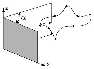
Figure 5‑7 Plane X-Axis
Using the “Plane X-axis” option, a plane passing through the Z-axis and rotated through an angle α from the X-axis. The elemental material angle is the angle between the intersection of this plane, or one parallel to it, with the element and the first edge of the element.
“Plane Y-axis” uses plane through X-axis measured from Y-axis.
“Plane Z-axis” uses plane through Y-axis measured from Z-axis.
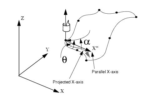
Figure 5‑8 Projected X-axis
Using the “Project X-axis” option, the global X-axis is projected normally onto the element at the first node. This axis is then rotated through the reference angle α in the counter (anti-) clockwise direction from the viewing point. It is important to note that the element material angle θ is generally not equal the angle α.
“Project Y-axis” uses the Y-axis
“Project Z-axis” uses the Z-axis
MSC.Laminate Modeler also allows the user to define angles with respect to the element datum (i.e., the first edge of the element). This feature can also be used to visualize the relative orientation of elements where this is not immediately obvious, such as if the pave mesher is utilized.
Practical Restrictions On Surfaces
The draping simulation has been found to give realistic results for surfaces which are manufacturable using sheet materials. This is even true for surfaces having infinite curvature in a single direction (i.e., sharp edges). However, the simulation is likely to fail where it is physically impossible to drape a real sheet of material.
Geometrical features leading to poor draping include:
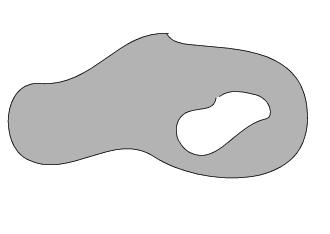
1. Excessive Gaussian Curvature. For example, the apex of a cone has extreme Gaussian curvature, and is therefore impossible to drape realistically. The user should use the Split Definition facility to cut the cone between its base and apex before simulating the drape.
2. Holes in Surfaces. It is recommended that holes be temporarily filled with dummy elements while a layup is being defined. If these elements are put in a separate Patran group, they can be excluded from the analysis by only analyzing the current group.
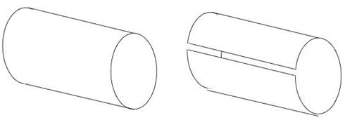
3. Incomplete Boundary Definition. Many surfaces, such as cylinders, do not have a complete boundary; draping will continue around the body until an internal program storage limit is reached. Define artificial boundaries using the split definition facility on the Create LM_Ply, Additional Controls, Definition form.
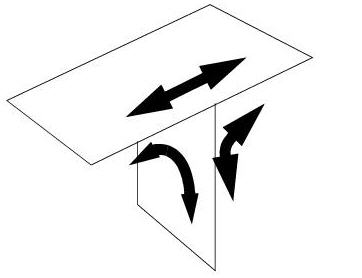
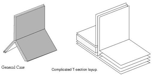
4. “T” Sections. These can be draped along three separate paths. The user must make sure that the correct elements are selected, and that a consistent definition of top and bottom surfaces is maintained. This prevent plies crossing over unexpectedly.